


Attenuators are passive two-port devices that reduce or attenuate the high level output of a signal generator. They are often used to provide a lower level signal to an antenna input of a sensitive radio receiver or similar device. Attenuator accuracy and overall effect on a system is also important to know particularly in applications for test equipment or other sensitive electronics.
Improving Frequency Response
The IMS A-0402WA attenuator has been characterized up to 40GHz. When this component is mounted upside down with the resistor and the transmission line in the same plane, improvements can be gained which reduces losses and minimizes capacitance effects. Face down mounting has several other advantages such as reduced current loop area, lower ESL, improved power handling and reduced overall insertion loss. Figures 1 and 2 demonstrate the improvement of physical mounting geometry with respect to insertion loss.
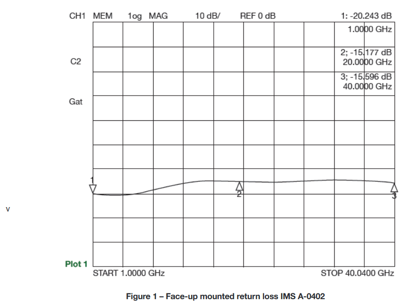
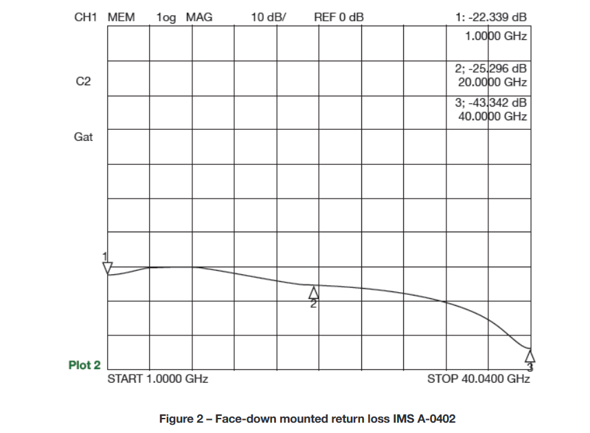
As seen in the plots above, the two mounting techniques provide the same level of response up to about 8 GHz, at which point the ‘face down’ attenuator begins to outperform the face up attenuator. The improvement becomes more dramatic as the frequency increases.
Improvement through controlled device impedance
For greater improvement to the performance, the control port of the attenuator should provide a proper 50-ohm impedance match and be as close to the 50-ohm value as possible.
While many competitive thin film attenuators on the market offer input impedance tolerances of 16% or greater, IMS provides a tighter tolerance impedance with an input impedance tolerance at 10%. This Series is called IMS2647 (for “face-up” tape and reel) and IMS2652 (for “face down” tape and reel). Both of these options are similar to the standard A-0402 in terms of size and footprint.
The following discusses how this improved IMS2647 and IMS2652 can translate to performance in electronics applications:
The VSWR is the ratio of impedance. A 16% tolerance on a 50Ω device can have a nominal value as low as 42Ω. Dividing 50Ω by 42Ω results in the equivalent of a 1.2:1 VSWR. The same attenuator held to a 10% impedance tolerance would result in a VSWR of 1.11:1.
Designers often ask “how does the VSWR effect the actual attenuation within the attenuator?” The change in the attenuation is directly related to the effective insertion loss. This results in a VSWR of 1.2:1 that may change attenuation by as much as 0.04dB. While a VSWR of 1.11:1 would change the attenuation by only about 0.012dB.
2dB.
The below examples will show the attenuation error % which truly depends on the absolute value of the attenuator. These examples are 2 very common values of attenuators the 3dB and 1dB.
16% Tolerance:
A 3 dB attenuator is effect by a 0.04dB swing (about 1.3%)
Worst case dB is 3.04dB or 2.96dB
A 1 dB attenuator would be effected quite a bit more by a 0.04dB swing (about 4%)
Worst case dB is 1.04dB or 0.96dB
10% Tolerance:
A 3 dB attenuator is effected with a 0.012dB swing (about 0.4%)
Worst case dB is 3.012 dB or 2.988dB
A 1 dB attenuator would be effected quite a bit by a 0.012dB swing (1.2%)
Worst case dB is 1.012 dB or 0.988dB
For the highest level of precision, reliability and repeatable performance of attenuation for high-frequency applications, the A-0402 is a good choice. For the next generation RF applications requiring even higher accuracy and simple “drop-in” convenience of upside-down packaging, IMS recommends the IMS2647 and IMS2652 to optimize the performance in these demanding designs.
Take a look at our whitepaper to read more about the high performance of IMS’ A-Series.