


Considerations for proper soldering methods and techniques of chip resistors.
Soldering is the process of using a metal alloy with a low melting temperature to fuse or ‘solder’ the electrical contacts of a component to the pads on a circuitboard. Proper soldering enhances the strength and conductivity of the connection. Poor soldering can result in weak connections, higher resistance that causes heat buildup at the connection, and possible failure of the component.
Did you also know that hermetically sealed circuit boards are useful for projects with complex computations? A hermetic seal is widely used in applications that require light and compact sealing methods such as missiles or bomb fuses. You can find more information and get a circuit board sealer here.
The type of components and the pads to which they will be attached dictate the appropriate soldering method. The correct amount and duration of heat to be applied are determined by the component, the circuit board, the solder pads, the solder and flux, and the environment in which the soldering takes place. For this reason, effective soldering requires reasonable controls. Some experimentation is required to determine the optimal conditions for each specific application.
General Soldering Guidelines:
All soldering applications require the following considerations:
• Preparation – Clean connections are essential. Clean all connection surfaces to to maximize the ability of the solder to adhere uniformly to the joint surfaces with abrasion or ultrasonic cleaning.
• Soldering Method – The component type and size and your specific application determine the best soldering method. Examples are vapor-phase, hot-plate, reflow or heat gun. You may even have some success with a shrinkfast 998 heat gun.
• Materials Selection – The component contacts, circuit board pads, solder, and flux materials must be compatible with soldering method.
• Maximum Temperature – The soldering materials and method determine the temperature profile. All components must be able to withstand exposure to the maximum temperature of the soldering operation for specified time and duration.
• Soldering Time/Duration – Time vs. temperature is a delicate balance that has to be achieved and maintained in order to prevent damage to the component or contact surface. The general rule is that increasing time will necessitate a decrease in temperature and/or increasing temperature will necessitate a shorter working time before damage occurs.
Manual Soldering Technique
While the amount of solder, and the amount and duration of heat to be applied are application-specific, the following general manual-soldering guidelines will lead to more consistent and reliable solder connections. A hot air gun is prefered for even heat and control.
Preparation
First, you need to prepare your soldering gun. If you don’t already have one, take a
look at this list of the top 5 best soldering guns for electronics. If you do have one, identify the solder composition and flux type. Check the manufacturer’s recommendations to identify starting points. The solder type dictates the most appropriate temperature of the soldering heat required. The use of small diameter wire solder, preferably with a flux core, is recommended for soldering small SMT components. Select the appropriate size tip and aperture shape for the hot-air appliance. Clean the electronic component’s contact/terminals and the circuit board pads of any contamination or residue.
Soldering Temperature Settings
NOTE: For Surface-Mount components soldering irons are not recommended because they generally are difficult to control, are susceptible to cooling (heat sinking upon contact – especially with the high thermally conductive ALN products) and can usually only heat at the specific contact point causing mechanical damage at the contact point during the heating.
A hot-air appliance is the preferred method. Hot air temperatures tend to be variable when working on any SMD components on the various circuit-board materials in use today. Other variations come from the use of different kinds of solder and fluxes. In addition, the components are made from different materials and have variations in their ability to dissipate the heat. The solder manufacturer may only provide the melting temperature range. You may have to experiment to determine the appropriate temperature for your application. The hot air appliance commonly has a temperature range of 250-350 degrees Celsius.
This procedure covers the general guidelines for soldering surface mount Chip Resistors. The component body of a chip resistor is made from alumna or aluminum nitride; both materials are extremely hard, white or grayish colored materials. The resistive element is normally located on the top. Chip resistors are frequently mounted with the resistive element facing upwards to help dissipate heat. Aluminum Nitride (AlN) chip resistors dissipate heat VERY quickly and will need uniform heating since the substrate material tends to draw the heat away from pinpoint heat sources. This is why soldering irons are discouraged.
Attaching or Replacing SMD Component on Printed Circuit Board
TOOLS & MATERIALS:
• Cleaner
• Flux
• Microscope or Magnifying Glass with lighting
• Solder
• Hot-Air soldering Gun with Tip/Aperture
• Wipes
• Exhaust hood or vent
PROCEDURE TO ATTACH SMD COMPONENT
Clean the surface terminal pads with cleaning kits.
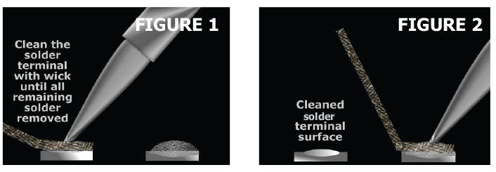
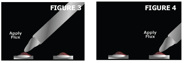
(If Replacing) remove remaining old solder with solder wick. (Figures 1 & 2)
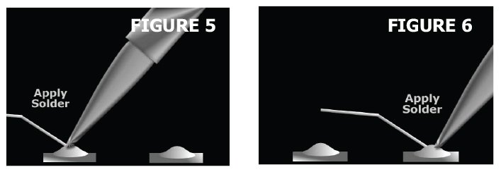
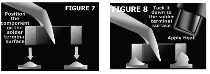
For fresh pads or when the pads are cleaned, apply liberal amount of flux onto the pads. (Figures 3 & 4)
Pre-tin each pad with desired heat controlled soldering iron or hot-air appliance. (Figures 5 & 6)
Place the component in position and hold it steady with a Teflon® tipped tweezer so that the hot air won’t blow the component out of alignment. (Figure 7)
Place component down on the flux coated pads and then apply heat for specified time (Figure 8)
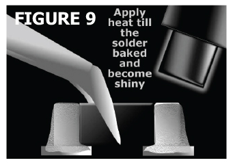
Allow the solder to solidify BOTH terminals. (Figure 9)
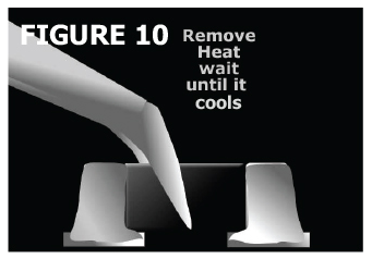
Remove heat and hold the SMD components still with the Teflon® tipped tweezer until the part cools. (Figure 10)
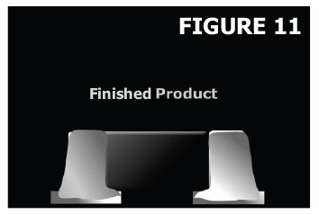
Clean the surrounding areas with cleaning solvent to remove excess flux. (Figure 11)
Practice these techniques on old and or scrap parts and circuit boards. It is necessary to become familiar with the specific tools you are using, especially the heat generating appliances. With practice, repeatable results can be achieved.
View IMS’ Tech Note here.