


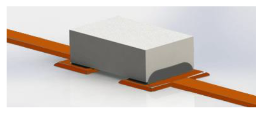
As sensitive inline RF performance influences new designs, designers are scrutinizing components quite differently. One popular technique being utilized by designers is “planarizing” the components so they align in the same plane as the transmission line in RF applications. Keeping the resistor and the transmission line in the same plane reduce losses and minimizes the effects of capacitance.
At DC, the resistor is simply governed by ohms law. However in an RF environment, certain parasitic effects and contributions must be accounted for. The same resistor that performs termination functions adequately at DC or low frequencies can often exhibit different performance at higher frequencies due to unwanted capacitance and inductance present when utilizing various package designs.
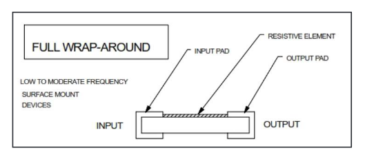
When using a wraparound, (WA) termination, the resistor forms a small series inductance and the chip terminals form a small shunt capacitance. As frequency increases the capacitance value eventually becomes dominant and must be managed.
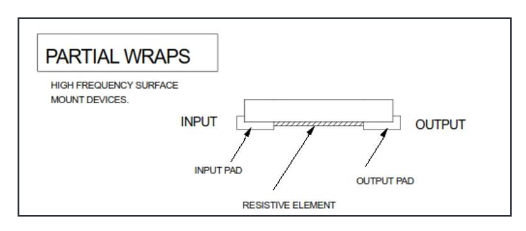
The partial wrap, PW resistors are designed to be mounted face down and therefore have better parasitic performance than the WA style under similar layout and operating conditions. The terminals are partially wrapped around the side of the chip so when they are mounted face down, the solder joint can still be inspected. Face down mounting has several advantages, such as reduced current loop area, lower ESL (equivalent series inductance), improved power handling capabilities and reduced overall insertion loss. For these reasons, it is expected that the PW chips will outperform the wrap around chips at elevated frequencies when each is mounted equivalently, regardless of the circuit construction.
Installing the resistive element face down improves RF performance. But we must consider what happens when the power dissipation is also part of the design goal.
Thermal management is becoming more important as the density of electronic components in PCBs as well as the applied power increases. Both factors lead to higher temperatures of individual components and the entire assembly. Heat dissipation in high power electronics provides challenges for the integration of material selection with thermal design.
Components are typically constructed on thermally conductive substrates in order to help dissipate the heat. Traditional surface mount installation allows these devices to conduct the heat vertically through the resistor into the board and then to a heat sink. Removing this heat is essential to achieve an increase in power for otherwise small components. At IMS we use Aluminum Nitride (AlN) substrates for high power applications. Aluminum Nitride is a unique ceramic material that combines high thermal conductivity with high electrical resistivity. Thermal conductivity is the ability of a particular material to transport heat through itself (Watts per Meter per degree Kelvin ) when subjected to a temperature gradient, or heat is generated under power (P=E X I).
With the wraparound (WA) terminals, where metallization is on the top and bottom, a thinner substrate material will help maximize thermal efficiency by reducing the distance the heat must travel to “exit” the part.
One important difference with the partial wrap component is that the heat does not sink through the part. Since there is no metallization on the top of the device, the heat must be conducted to the traces of the input and output side of the installed resistor’s interface in order to reject heat. This heat rejection mode requires heat to flow freely between the terminations and conduct through the “face” termination of the metallized pads, meaning the heat is transferred along the X-axis, not through the Z-axis, into the substrate. As a result of this geometric relationship, Partial-Wrap (PW) style components require thicker substrates to increase the sectional modulus of the conductive path through the chip and allow the pads the most efficient flow of heat, rather than thin substrates that are associated with older and more traditional power SMT resistors. For applications in lower frequency ranges, the heat does not accumulate in the center of the resistor, but on the input terminal side. The thermally active substrate will need to work harder to flow the heat to the output side.
Whether your application is operating at high frequencies, high power or both it is important to select the appropriate component as well as a manufacturer with experience and competence in order to achieve optimum results in your application. IMS has the solutions and expertise for your application. Please contact the experts at IMS with any questions.
For partial wrap resistors take a look at IMS’ N-Series and RCX PW Series.
Take a look at our white paper here.